Noise and vibration testing is a crucial challenge for many companies, whether they have a large engineering staff or they are a small company being asked to do this for the first time. It can be a perfect solution to take advantage of Brüel & Kjær engineering services at the ARC because it has product development labs, engineering simulation facilities, and state-of-the-art testing hardware all in one place.
In addition to all the latest types of test equipment, applications, and solutions, this rare one-stop facility has the expertise of dedicated Brüel & Kjær staff on hand to help gain insights and find effective engineering strategies.
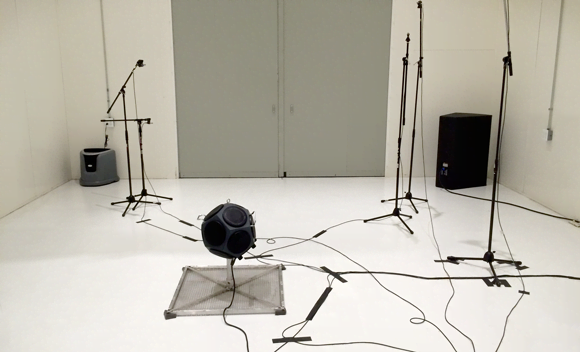
Reverberation chamber
PRODUCT NOISE TESTING
The hemi-anechoic chambers are intended for measurements where you want to be sure that the sound is not reflected and measured more than once. The opposite of this is the reverberation chamber, where you want the sound to reflect as much as possible. In the reverberation chamber, the goal is to have a uniform sound field at any given point in the room. This is useful for transmission loss tests and also for sound power tests. Sound power is a measure of the acoustic energy being radiated by a test subject. These tests are usually controlled by standards that dictate the number and positions of microphones to be used and are specific to the application.
Types of tests
- Transmission loss testing
- Sound power testing
Typical test objects include:
- Household appliances (for example, dishwashers and vacuum cleaners)
- Other consumer products (for example, power generators and concrete saws)
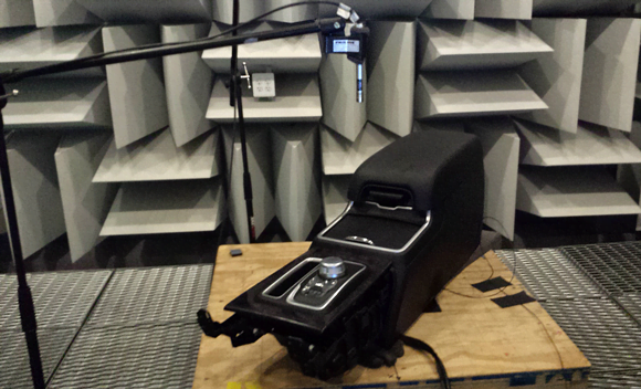
Full Anechoic Chamber (FAC)
Similar to the structural hemi-anechoic chamber (SHAC), the purpose of the full anechoic chamber (FAC) is also to avoid any reflections for very precise measurements. The FAC is smaller in volume and the sound-absorbent cones used on the walls in the SHAC and the AHAC are also used on the floor, for further reduction in reverberation. There is a port in one of the walls adjacent to the reverberation chamber, which can be used to mount samples for transmission loss testing. Since the ambient noise level in the FAC is much lower than in the other chambers, it is a good resource for test subjects that produce very little sound.
Types of tests
- General troubleshooting
- ISO or OEM standardized tests for automotive suppliers
- Transmission loss testing
Typical test objects include:
- Very quiet products, such as computer components
- Individual automotive parts, such as transmission shifters
- Medical instruments
Structural Hemi-Anechoic Chamber (SHAC)
The structural hemi-anechoic chamber (SHAC) is the most commonly-used test chamber at the ARC because of its broad dimensions and versatile accommodation. It is equipped with a large steel bedplate floor with T-slots that make it very convenient for structural component testing.
It also has a 10-ton overhead crane mounted near the ceiling for handling large materials or even for full-vehicle body separation and lifting. This chamber also has exhaust extraction capability and a CO2 monitoring system, so a vehicle’s engine can be operated without concern. It is located near the building’s utilities, so it is convenient for products that require compressed air, 110 or 220-volt electricity, or water.
Types of tests
- Structural component testing
- Modal testing
- Sound power testing
Typical test objects include:
- Consumer products, such as dishwashers, refrigerators, or food-waste disposers
- Vehicle components from exhaust systems to electric parking brakes
- Large materials and full vehicles
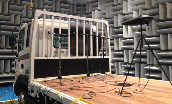
Acoustic Hemi-Anechoic Chamber (AHAC)
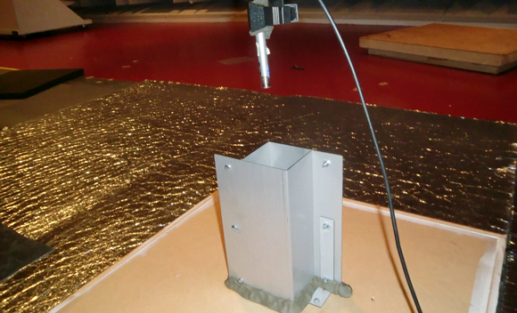
The acoustic hemi-anechoic chamber (AHAC) is also commonly used as a general-purpose test cell, but it has its own unique features. While it has the same physical dimensions and similar acoustic properties as the SHAC, it is intended to be used in transmission loss tests.
The AHAC is adjacent to two reverberation chambers – one below the test cell, the other to its side. The fundamental theory behind transmission loss testing is to mount a test article between two opposing acoustic conditions – one that is uniformly loud (reverberant), and another that is uniformly quiet and free from echoes (anechoic).
A test article is normally mounted in a wooden buck, which is thoroughly sealed around its edges. Sound (close to 120 dBA) is blasted at the test article from within the reverberation chamber. A beamforming array or sound intensity probe is used on the quiet side of the test part to understand the location and frequency content of any weak spots. The reverberation chambers, both above and below the AHAC, allow a part to be mounted just as it would be in real life, allowing accurate representation of its in-service attenuation performance.
Types of tests
- Transmission loss testing
Typical test objects include:
- Large panels – such as a vehicle’s floor plan
- Sealant products of various compositions
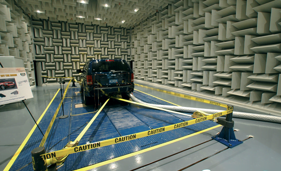
4-Wheel-Drive Chassis Dynamometer
While the SHAC has exhaust extraction, which allows staff to test a running engine in a vehicle, this is rarely enough information to resolve a complex issue. In normal road driving, a vehicle’s powertrain behaves very differently, which changes the sound and vibration characteristics dramatically.
This is where the 4-wheel-drive chassis dynamometer comes in. It provides a repeatable way to test a vehicle’s powertrain and drivetrain under load, allowing engineers to test a vehicle under extremely controlled conditions that simulate driving it on the road. It is also pretty nice, for example, to be able to test a vehicle during Michigan’s winter without worrying about snow!
Engineers can control the temperature and humidity of the room while the dynamometer is in operation to ensure the powertrain experiences test conditions are as faithful as possible. And to replicate the effects of a rough road in a repeatable way, an alternative ‘road shell’ can be added to the dynamometer’s rollers.
VEHICLE NOISE, VIBRATION AND HARSHNESS (NVH)
The rear axle of the dynamometer can be easily moved to accommodate the wheelbase of many vehicles. The machine’s front and rear motors are each capable of providing or absorbing up to 300 horsepower.
This means that the vehicle can be driven normally while the dyno is used to absorb the torque from the wheels or that the dyno can be used to spin the tires and drivetrain of the vehicle. The torque from the motors allows engineers to control the vehicle in many configurations to problem-solve sound and vibration issues.
Types of tests
- Vehicles’ powertrain and drivetrain under load
- Automotive benchmark tests
Typical test objects include:
- All types of vehicles – from small sports sedans to flat-bed commercial trucks
Abonnieren Sie unseren Newsletter zum Thema Schall und Schwingung
Die aktuellsten Neuigkeiten von Brüel & Kjær direkt in Ihren Posteingang
Neue Produktfreigaben, Rabatte und Sonderangebote
Artikel, Videos und Anleitungen zum Thema Schall und Schwingung