In 2003, the Institute of Space and Astronautical Science (ISAS), the National Aerospace Laboratory of Japan (NAL) and the National Space Development Agency of Japan (NASDA) merged to become the Japan Aerospace Exploration Agency (JAXA). JAXA, as of 2015, is part of Japan’s National Research and Development Agency, supporting the government’s overall goal to use space for the betterment of society.
Getting a payload into orbit is an expensive affair, and not just for the launch itself. The payload, more often than not, represents millions of dollars of design, components, testing and man-hours. So, after all that expense, it is supremely important to take every precaution necessary to ensure that the investment makes it to orbit successfully.
The most publicized method is stress testing the payload itself to ensure that it can survive the stresses of launch unscathed.
But what if the overall stresses of the launch could be reduced?
With the introduction of their new Epsilon launch vehicle in 2013, JAXA targeted one of the contributors to the overall vibration. There are myriad contribution paths in any given structure, and the more complicated the structure, the greater the number of paths. Some paths are more apparent than others, and some are more or less malleable than others.
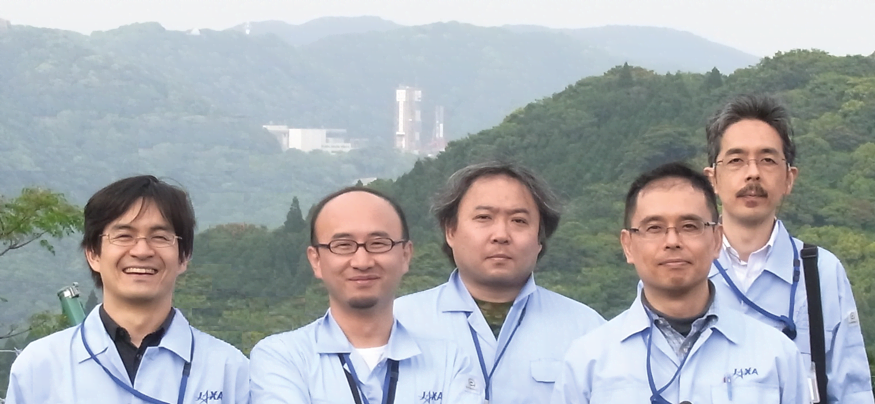
Epsilon Launchpad Team
A special acoustic team requested by Epsilon rocket project was formed in JAXA to tackle the potential acoustic problems. In the team, led by Tatsuya Ishii, and joined by Yutaka Ishii and Hiroshi Komatsuzaki of Brüel & Kjær are tasked with focusing on an area that wouldn’t be immediately obvious to the uninitiated: Acoustically transmitted vibration from the rocket motor bouncing back up from the launchpad to affect the payload.
Tatsuya Ishii received his PhD in mechanical engineering from the University of Tokyo and began his career at NAL in 1994, merging with JAXA in 2003. He is now a manager of engine acoustics in the Propulsion Research Unit of the Aeronautical Technology Directorate. Tatsuya is currently engaged in acoustic studies regarding aircraft engine noise, particularly jet noise reduction, active noise control, sound source localization, acoustic absorption and launch vehicle acoustics.
Redesigning a Launchpad
Airborne vibration actually contributes a surprising amount. During lift-off, the plume coming from the base of the rocket is not just the cloud of fire and smoke that spectators see from a distance, it is a very high-speed exhaust plume containing powerful shockwaves that radiate high levels of sound power that reflect from the surrounding environment, like the launchpad. The combined acoustic effects of this extremely harsh environment can potentially damage the payload.
In preparation for this project, computational and experimental projects were undertaken to understand the components and sound contributors and validate the acoustic environment around the vehicle. The results of these two preliminary projects indicated that the launchpad itself needed a major overhaul.
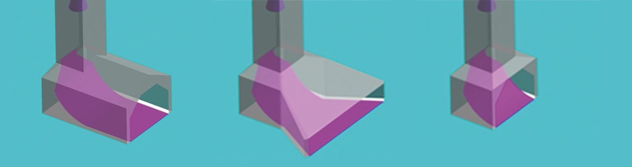
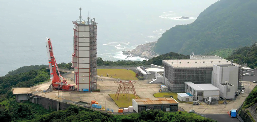
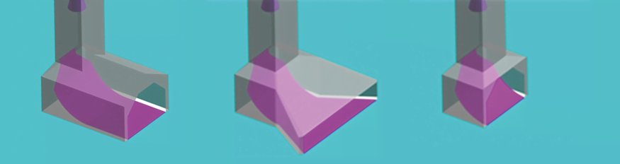
In order to mitigate this contribution path, JAXA began the process of redesigning the launchpad to deflect the extreme sound pressure away from the payload. To do this, they would need to find the optimal design that would most effectively protect the rocket and its payload from the plume and its contained shock-wave noise source. Through designing with numerical models, CFD finally proposed a couple of optimal entire launchpad models. Obviously, constructing multiple full-scale launchpads and performing multiple full-scale launches in order to test the possible designs would be prohibitively expensive.
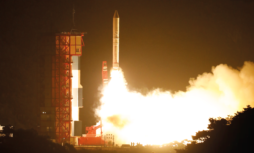
Epsilon launch vehicles are solid-propellant, three-stage motor systems designed to transport a payload of up to 1.2 tons to LEO
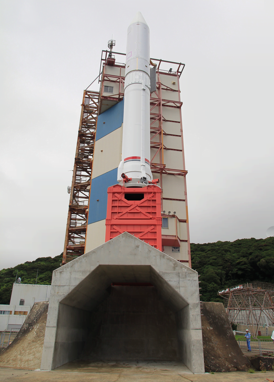
Epsilon-1 launch vehicle preparing for launch on the new launchpad.
LEARN MORE
HYDROPHONES
Array Geometry: Scaled for convenience
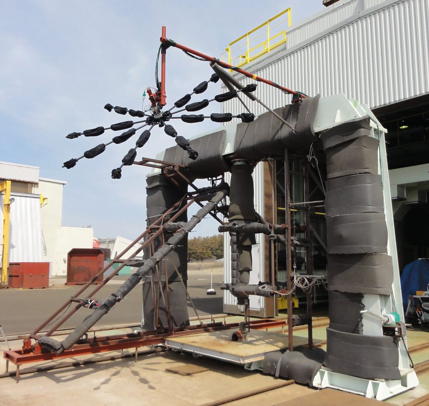
The local conditions around the scale model are not as extreme as around the full-scale system, so the equipment used would not need to meet the harsher requirements of the real environment. An added benefit of a scaled-down model is that the pertinent frequencies are scaled up, which means that sufficient resolution can be achieved with a much smaller and more manageable array than the full-scale system.
Array geometry is a key factor in obtaining good results from a beamforming system. A good array geometry is characterized by having a low maximum sidelobe level (MSL). For a measurement on a single small source, MSL is the difference in decibels between the true noise source and the strongest ghost source in the beamformed map. However, since the ghost source pattern is known (defined by the array geometry), it can be com-putationally removed by a so-called deconvolution algorithm.
To determine the contributions to the sound pressure at the payload, the array should ideally be placed at the payload and focused towards the dominant noise source (in other words, the plume). However, because of the interference of the support structure around the model and the need to avoid the fire of the rocket, the array was offset and placed at the minimum angle possible from the vertical direction.
The scaled measurements and the resulting data were analysed, and based on the results, the final launchpad design was chosen. The next phase was construction and then application of the full-scale system and testing to confirm correlation between the small-scale and full-scale systems.
LEARN MORE
MICROPHONE ARRAY SYSTEMS
Scale-Model Array Setup
LEARN MORE
LAN-XI DAQ FRONTENDS
Type-1
Type 2 (63hz, 125 Hz and 250Hz):
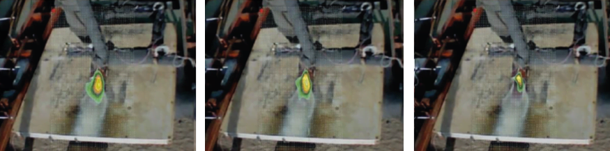
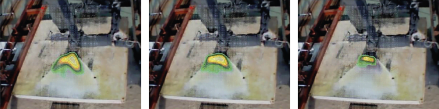
Noise source identification overlay of scale-model test
A Very Large Array System
The full-scale measurement required additional mitigations. Due to the extreme environment near the launchpad, the array would need to be placed 70 metres from the launchpad. This solved the temperature problem but presented additional issues. Because the very low frequencies were the primary interest and because of the distance from the launchpad, a very large array was required to provide any useful resolution.
Fortunately, the most important resolution of interest was only along the horizontal plane through the rocket nozzle and the deflector outlet, assuming that the two main sources radiate omnidirectionally, eliminating the need to locate the array near the payload. This meant that the task could be performed by a horizontal line array on the ground.
Two additional issues encountered in the full-scale measurement were flow noise, which comes from the rocket motor exhaust blowing air and debris in the direction of the array, and very high sound pressure levels. Both of these issues were resolved using a solution that might not sound immediately obvious:
Hydrophone Measurements
Measurements were made with two Brüel & Kjær Type 8103 hydrophones during the first Epsilon launch to confirm time data correlation to microphones. Due to the advantages they offer when measuring high sound pressure levels in air and their demonstrated ability to provide quality data, hydrophones were chosen for the array that would measure both the Epsilon-2 and Epsilon-3 launches.
Brüel & Kjær hydrophones are suitable for a wide range of applications in industry and research.
> Explore our Hydrophones
The very high sound pressure levels were accommodated through the hydrophone’s design – they can deal with extremely high sound pressure levels. And flow noise, which interferes with the measurement and corrupts data, is minimized due to the aerodynamic shape of hydrophones.
Validating a proven process
Throughout the process, the JAXA team was focused on a singular target:
Make the payload safer.
Through a proven process of identifying the problem, testing solutions and validating results, they succeeded. The data gathered during the small-scale tests that yielded their final launchpad design was validated and, in real-world application, proven to have substantially reduced the acoustic vibration, and thereby the overall vibration affecting the payload.
RELATED WAVES ARTICLES
Abonnieren Sie unseren Newsletter zum Thema Schall und Schwingung
Die aktuellsten Neuigkeiten von Brüel & Kjær direkt in Ihren Posteingang
Neue Produktfreigaben, Rabatte und Sonderangebote
Artikel, Videos und Anleitungen zum Thema Schall und Schwingung