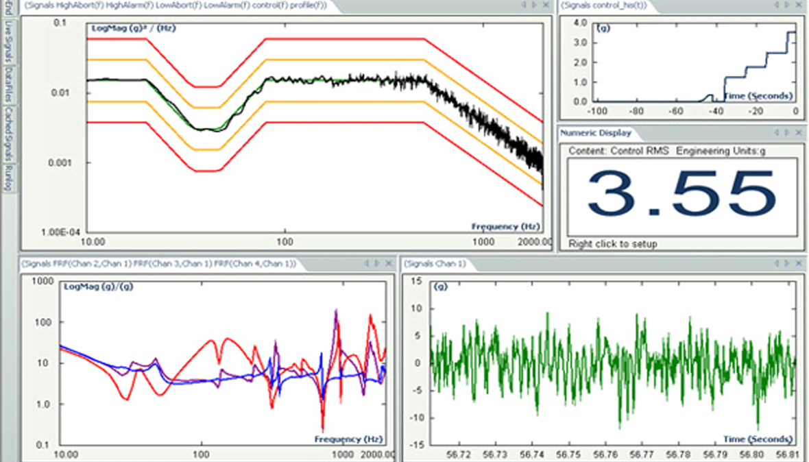
Vibration Test Profile
Random Vibration control
A vibration controller feature used within a closed-loop test system to produce a random signal that simulates a broad range of real-world operating environments.
Solicitar ofertaThe random vibration (or excitation) test profile simultaneously excites all resonant frequencies of any given payload, thus it is well suited for product qualification tests and for characterizing a structure’s dynamics. A fast loop time is important for high accuracy, and so are multi-channel control, notching, and real-time analysis.
USE SCENARIOS
- Simulation of vibration experienced by components and assemblies used in automobiles, military vehicles, aircraft and space vehicles
- Replication of field measurements
- Production testing, stress screening and prototype testing
- Product qualification to MIL-STD, DIN, ISO, IEC and other standards
CHARACTERISTICS
A random test entails configuring the parameters via the host PC by entering a chosen PSD (power spectral density) into a simple breakpoint table, or by importing previously-gathered field data in Microsoft Excel® CSV (comma-separated values) format. The breakpoint table consists of PSD amplitudes and associated frequencies, plus slope segments. The frequency range is specified, say from DC to 4800 Hz.
When slopes are used, the table automatically calculates crossover frequencies and PSD amplitudes. As the breakpoint table is created, a plot displays the profile. The overall RMS (root mean square) value, maximum peak velocity, and maximum peak-to-peak displacement for the full-level test are automatically displayed.
A spectral resolution in terms of FFT (Fast Fourier Transform) lines will be specified. The greater the number of lines, the smaller the frequency delta between each line. For example, 1600 lines with a frequency range of 4800 Hz gives a resolution of 3 Hz. There may be an option to increase the spectral resolution at the expense of the number of input channels.
A dynamic control range will be specified, say 90 dB. This defines the maximum slope, or rate of change, of the control output. A higher value will yield a more severe test of the payload.
To prevent malfunctions or damage to the device under test and to the equipment, if the dynamic demands of the test exceed the shaker system’s limits, the user will be warned automatically.

Suscríbase a nuestro boletín informativo y recibirá las últimas noticias de B&K sobre sonido y vibración

