
MACDARA MACCAMHAOIL | BRÜEL & KJÆR
DOWNLOAD PDF
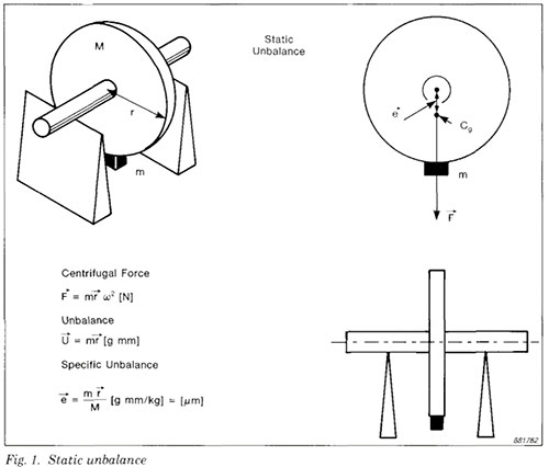
Unbalance in a rotor is the result of an uneven distribution of mass, which causes the rotor to vibrate.
The vibration is produced by the interaction of an unbalanced mass component with the radial acceleration due to rotation, which together generate a centrifugal force. Since the mass component rotates, the force also rotates and tries to move the rotor along the line of action of the force. The vibration will be transmitted to the rotor's bearings, and any point on the bearing will experience this force once per revolution.
Balancing is the process of attempting to improve the mass distribution of a rotor, so that it rotates in its bearings without uncompensated centrifugal forces. This is usually done by adding compensating masses to the rotor at prescribed locations. It can also be done by removing fixed quantities of material, for example by drilling.
Static Balancing involves resolving primary forces into one plane and adding a correction mass in that plane only. Many rotating parts which have most of their mass concentrated in or very near one plane, such as flywheels, grindstones, car wheels, etc., can be treated as static balancing problems. If a rotor has a diameter of more than 7 to 10 times its width, it is usually treated as a single-plane rotor.
Dynamic Rotor: Unbalance Calculations
The calculation of the maximum allowable residual specific unbalance assumes that the mass of the rotor is evenly distributed about the centre of gravity. If the mass of the rotor is unevenly distributed, the calculations are a little more complicated.
In a perfectly balanced rotor, equal forces act on both ends of the rotor when it rotates. If the rotor is shaped as in Fig. 8, however, the forces at each end will be equal, but the allowable residual specific unbalance will be different for each bearing. The position of the centre of gravity divides the rotor in the ratio V3 : 2 /3. The sum of the moments about the centre of gravity must be zero. Therefore the residual specific unbalance at bearing A is 2 /3 of the total residual specific unbalance, while at bearing B it is V3 of the total.
Selection of Trial Masses
The specific unbalance is used to calculate the size of trial masses, which are used during balancing to make temporary alterations to the mass distribution of the rotor, to determine the relationship between the specific unbalance and the bearing vibrations.
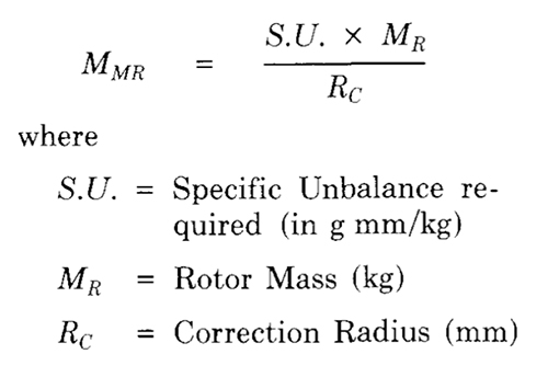
To estimate the value ol a suitable trial mass, the mass oi the rotor in kg and the radius m mm at which the corrections are to be made must be determined. The Maximum Residual MMR, in grammes, is given by:
A suitable trial mass is five to ten times the value of the Maximum Residual Mass.
RELATED ARTICLES
Download the full handbook
Please sign in to download.
Sign-up is free and gives you full access to our Knowledge Center, with guides, primers and handbooks, technical notes and more.