Accelerometri
Gli accelerometri utilizzano un sistema a molla di massa per generare una forza proporzionale alla vibrazione. Brüel & Kjær offre un ampio spettro di soluzioni accelerometro che rispondono a diverse esigenze e applicazioni. Questa adattabilità è evidente nella gamma di trasduttori progettati per ambienti, settori, compiti e condizioni specifici, nonché strumenti di uso generale che forniscono un'ampia gamma operativa.
Selecting an Accelerometer-
CCLD - IEPE Accelerometers
B&K CCLD accelerometers are designed to make vibration measurement easy because the preamplifier is built into the accelerometer. They features low impedance output enabling the use of an inexpensive and long cables.
-
Charge Accelerometers
A charge‐type piezoelectric accelerometer is robust and designed specifically for high‐temperature vibration measurement. The unique design of our charge sensors delivers a high dynamic range, long‐term stability, and ruggedness.


1. What Is An Accelerometer?
2. Single or Triaxial Accelerometers?
3. Preamplifiers
4. Selecting Your Accelerometer
What Is An Accelerometer?
An accelerometer is an electromechanical transducer that produces at its output terminals an electrical output proportional to the acceleration to which it is subjected. The output signal can be electronically processed and read on a meter or some other suitable indicating device.
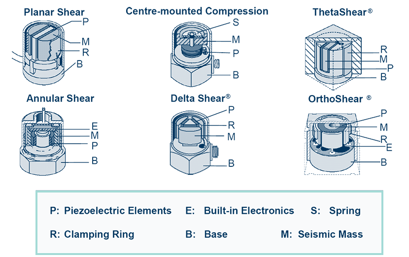
The active element of Brüel & Kjær vibration sensors consists of piezoelectric discs or slices loaded by seismic masses and held in position by a clamping arrangement.
The piezoelectric elements produce a charge proportional to the applied force. When the sensor is subjected to vibration, the combined seismic mass exerts a variable force on the piezoelectric element, proportional to the acceleration of the seismic masses.
An accelerometer for vibration measurement exhibits better all-round characteristics than any other type of vibration transducer. Providing wide frequency and dynamic ranges and good linearity throughout the ranges. There are no moving parts within the sensor, making it robust and reliable, with characteristics that remain stable over a long period of time.
The different designs and elements of an accelerometer:
Accelerometer Preamplifier
With the exception of DeltaTron accelerometers that have built-in preamplifiers, the outputs from Brüel & Kjær charge accelerometers need to be fed through a preamplifier.
Charge amplifiers are recommended, and Brüel & Kjær produce a wide selection of high-performance preamplifiers for this purpose. With charge preamplifiers, you are able to use very long connection cables without altering the specified sensitivity of the accelerometer and preamplifier combination.
Since ease of calibration and measurement are usually just as important as overall gain and frequency range, most Brüel & Kjær accelerometer preamplifiers have one or more of the following signal conditioning aids:
SIGNAL CONDITIONING
- Sensitivity Conditioning Networks : Allow direct dial-in of transducer sensitivity on the preamplifier, giving unified system sensitivities.
- Integration Networks : Automatically convert measured acceleration to a velocity and displacement proportional signal.
- High- and Low-pass Filters : Permit selection of different lower and upper frequency limits on the preamplifier to exclude unwanted signals and the influence of the sensor resonance from measurements.
Single- or Triaxial Accelerometers?
Triaxial accelerometers ( also referred to as 3-axial accelerometers, or 3 axis accelerometer ) are used for vibration measurements in three mutually perpendicular directions (axes) simultaneously. As a rule of thumb triaxial accelerometers provide more measurement information than regular single axis sensors.
Normally, triaxial accelerometers consist of three individual accelerometers mounted in a single housing 90 degrees apart. However, this limits the minimum size of the accelerometer and means that each axis has a different point of reference.
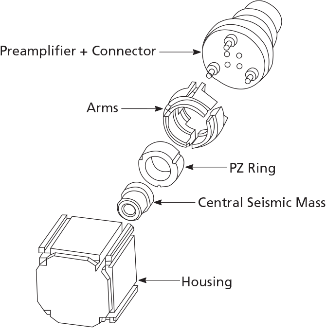
Brüel & Kjær's accelerometers use a common seismic mass and piezoelectric element.
This design results in a very compact triaxial accelerometer where all the axes have the same point of reference. Its design also ensures accurate and consistent measurements, even when the accelerometer is exposed to complex vibration patterns.
Selecting Your Accelerometer
When selecting your accelerometer, these are the specifications you need to be aware of to achieve the best results for your test application and environment:
SPECIFICATIONS
> Uni-gain and "V"
> Sensitivity
> Freq. Response
> Dynamic Range
> Calibration
Uni-Gain and "V"
We list both “V” types as well as Uni-Gain sensor types:
The “V” Types: The sensors without Uni-Gain types are recognized by the “V” suffix in the type name. The difference between these two types is that all the specifications on the calibration chart for “V” types (except the sensitivity), are typical.
In contrast, the sensitivity and other parameters for the Uni-Gain sensor types are guaranteed within tight tolerances for easy interchangeability without recalibration.
Uni-Gain Sensitivity: This designation indicates that the measured accelerometer sensitivity has been adjusted during manufacture to within 2% of a convenient value, for example (in 10 dB steps), 1, 3.16, or 10 pC/ms –2 .
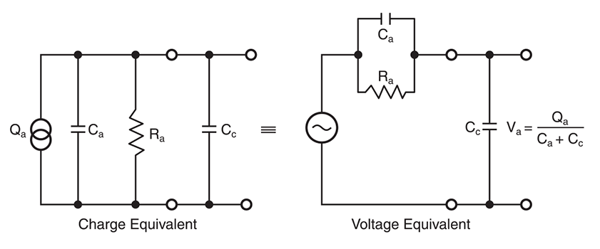
Charge and Voltage Sensitivity
A piezoelectric accelerometer may be treated as a charge or voltage source. Sensor sensitivity is defined as the ratio of its output to the acceleration it is subjected to. This is expressed in terms of charge per unit acceleration (e.g. pC/ms –2 ) or in terms of voltage per unit acceleration (e.g., mV/ms –2 ).
The sensitivities given in the individual calibration charts have been measured at 160 Hz with an acceleration of 100 ms –2 . For a 99.9% confidence level, the accuracy of the factory calibration is ± 2% and includes the influence of the connecting cable supplied with the accelerometer.
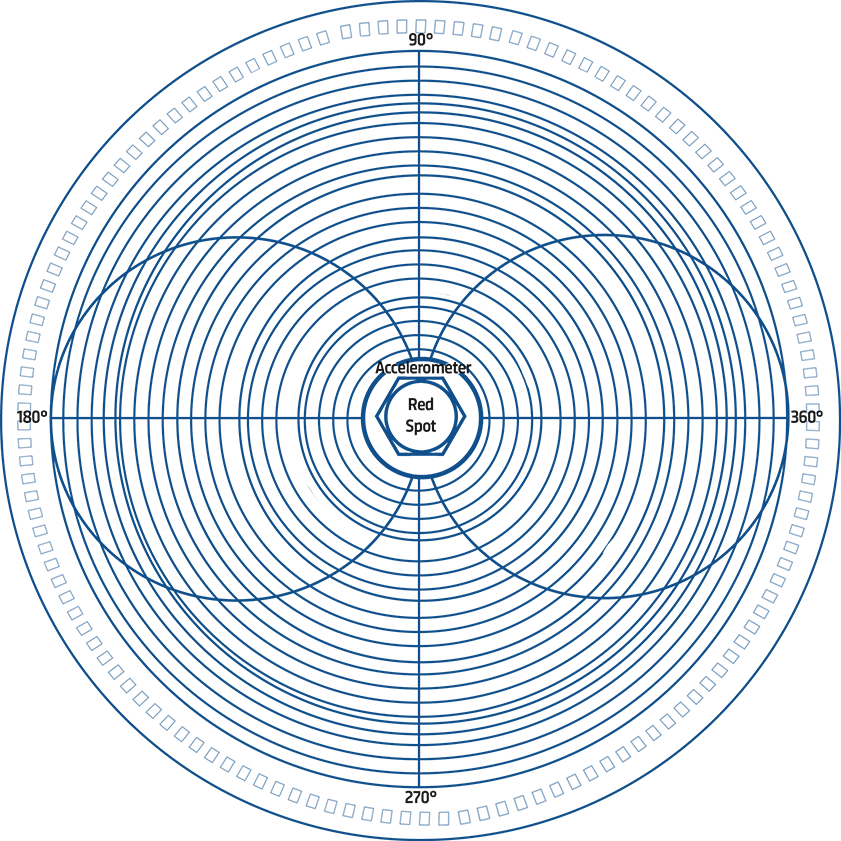
Transverse Sensitivity
Accelerometers are slightly sensitive to acceleration normal to their main sensitivity axis. This transverse sensitivity is measured during the factory calibration process using a 30 Hz and 100 ms –2 excitation and is given as a percentage of the corresponding main axis sensitivity.
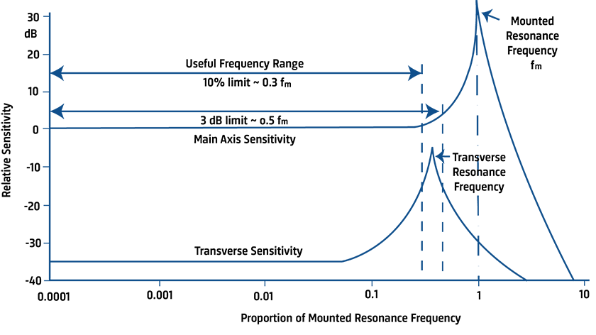
Frequency Response and Range
The upper-frequency limits give n in the specifications are calculated as 30% and 22% of the mounted resonance frequency to give errors of less than 10% and 5% respectively. These calculations assume that the sensor is properly fixed to the test specimen, as poor mounting can have a marked effect on the mounted resonance frequency.
The low-frequency response of an accelerometer depends primarily on the type of preamplifier used in the measurement setup.
Transverse Resonance Frequency: Typical values for the transverse resonance frequency are obtained by vibrating the sensor mounted on the side of a steel or beryllium cube using Calibration Exciter Type 4294.
Phase Response and Damping: The low damping of Brüel & Kjær accelerometers leads to the single, well-defined resonance peak plotted on the individual frequency-response curves.
Dynamic Range: Upper and Lower Limit
The dynamic range defines the range over which its electrical output is directly proportional to the acceleration applied to its base.
Upper Limit: In general, the smaller the device, the higher the vibration level at which it can be used. The upper limit depends on the type of vibration, and is determined by the pre-stressing of the piezoelectric element as well as by the mechanical strength of the element.
For accelerometers with built-in preamplifiers, the maximum shock and continuous vibration limits listed in the Specifications are measuring limits. For transportation and handling, the maximum non-destructive shock is specified and the maximum shock and continuous vibration limits are specified for any direction for frequencies of up to one third of the mounted resonance frequency.
When measuring short duration transient signals, care must be taken to avoid ringing effects due to the high-frequency resonance of the sensor. A general rule of thumb for a half sine shock pulse to obtain amplitude errors of less than 5% is to ensure that the duration of the pulse exceeds 10/ /f/R, where /f/R is the mounted resonance frequency of the accelerometer.
Lower Limit: Theoretically, the output of a piezoelectric sensor is linear down to the acceleration of the seismic mass due to the thermal noise, but a practical lower limit is imposed by the noise level of the measurement system and by the environment in which measurements are made.
Calibration and Stability
Brüel & Kjær accelerometers are thoroughly checked and examined at all stages of manufacture and assembly. Each device undergoes an extensive calibration procedure and artificial ageing process so as to ensure completely predictable performance and stable operation.
Calibration of Brüel & Kjær transducers is performed by back-to-back comparison with a primary reference standard accelerometer, calibrated at the Danish Primary Laboratory of Acoustics (DPLA), and checked by the American National Institute of Science and Technology (NIST), and the German Physikalisch–Technische Bundesanstalt (PTB) for traceability.
The overall accuracy of the back-to-back comparison is 2% with a 99.9% confidence level (1.6% for a 99% confidence level), while for the interferometry method the accuracy is better than ± 0.6% with a 99% confidence level.
 LEARN MORE
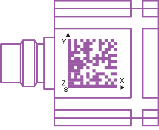
 TRANSDUCER SMART SETUP
To simplify multi-channel setups our Transducer Smart Setup App provides the ideal solution. The app works in combination with data matrix codes (similar to QR codes™) placed on the sensors, providing instant access to specifications and calibration.
Get in Touch!
For further details or questions in regard to specific sensor types, specifications and price, please get in touch with your local Brüel & Kjær sales representative.

Parla oggi stesso con il tuo rappresentante locale Brüel & Kjær!
Selezione della strumentazione giusta per la tua misurazione
Configurazione della strumentazione tecnica e assistenza alla misurazione
Domande generali e supporto