Noise intrusions are characterized by their high-intensity, transient quality – typical examples are motorbikes, trucks, aircraft, road drills, and sirens.
Their noise stands out far above all other sounds, and due to their detrimental nature, national standards limit their maximum allowable noise emissions. Ambient noise, when too great for a sustained period is associated with health issues like stress, increased blood pressure, and hearing loss.
Marine Noise Pollution
Let's make it clear: Regulation ranges from sparse to non-existent. And this is despite multiple studies that show noise pollution to be as, if not more, detrimental to marine life as it is to people.
In reality, we share many of the same consequences – increased stress levels, hearing loss, disrupted sleep, and communication interference – but much of marine life, mammals, in particular, use sound for navigation, prey and predator detection, which isn’t just a stressor, it’s potentially fatal short term.
Until fairly recently, the debate on how marine mammals are affected by anthropogenic noise mostly centered around what would be considered noise intrusions – naval sonar testing and air bursts used in the detection of fossil fuels, for example.
But studies are beginning to focus more on the ambient noise environment, which includes commercial vessels. Many of the findings point to avoidance behavior, problems communicating, finding mates, finding food, and avoiding predators.
KRISO (Korea Research Institute of Ships & Ocean Engineering)For more information on the project, subsequent research, and other KRISO projects, visit:
> KRISO Website
KRISO is a leader in ship and ocean engineering technology development.
One of its focus areas is researching environmentally friendly shipping technology. Understanding propeller noise is an important aspect of that focus area.
Propeller noise particularly turns (as spectral harmonics) and cavitation (as broadband noise), is one of the dominant sources of marine vehicle noise, and a prevalent source of marine noise pollution.
The need to develop a low-noise propeller has become more and more important as the detrimental effects of marine noise pollution become more understood and more commonly observable. A propeller research team at KRISO is using their Large Cavitation Tunnel (LCT), to do just that.
Scaled-down Model For Testing
Obviously, constructing full-scale ships for testing then redesign and construction anew, is prohibitively expensive.
That means testing on scale models, which of course presents another set of problems, such as scaling effects and multi-path reflections in cavitation tunnels. So an effective scaled-down model propeller noise testing procedure must be investigated.
To successfully do this, the propeller noise source mechanism must be understood so that its noise profile can be predicted and controlled in the full-scale ship design stage.
Measuring Propeller Noise
According to their research, single hydrophones can be used when propeller noise is greater than the background noise, but not if the noise level is comparable to, or lower than, the background noise. Using hydrophone arrays is a way to get around this problem.
Most large cavitation tunnels use an array system that is installed inside an acoustic trough and isolated using acoustic windows, but accuracy is degraded by multi-path reflections in cavitation tunnels. The team’s goal was to find an array design optimization technique for cavitation tunnel noise measurements and, in the process, find the best fit for their LCT for minimizing the effect of multi-path reflections.
Their optimization technique begins with establishing design parameters for the various array setups understudy, then proceeds to the objective function, which was to simultaneously examine the main-lobe beamwidth and maximum side-lobe level and finally apply global optimization using very fast simulated re-annealing (VFSR).
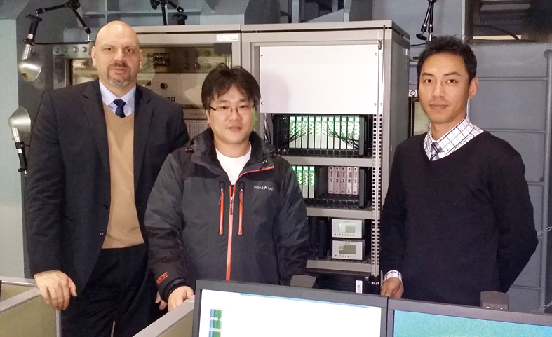
From left:
Key Account Manager Patrick Wethly (Brüel & Kjær)
Senior Researcher/Ph.D. Mr. Hanshin Seol (KRISO)
Sales Engineer Hyun Ju Yoon (Brüel & Kjær Korea)
The KRISO team uses beamforming and a 45-channel hydrophone array, based on Brüel & Kjær Hydrophone Type 8103 + LAN-XI Data Acquisition System and PULSE™. In their selection process for the best-suited array, they looked at four hydrophone array set-ups on a 1.6 × 1.6 m frame and a minimum hydrophone spacing of 4 cm.
Hydrophone Beamforming Array
They succeeded in finding the optimum design of a beamforming array and verifying their optimization technique. After applying the VFSR optimization method to minimize the object function and analyzing the data, circular array (case 2) and multi-spiral array (case 4) showed good performance in terms of minimum side lobe with 100 iterations.
The process continues to provide results and has yielded continued research in the LCT where the team continues to explore the benefits and challenges of studying marine noise in a scaled environment.
LEARN MORE
HYDROPHONES
Hydrophone Array Setups
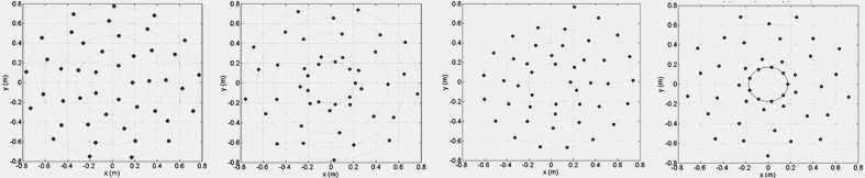
Case 1 - Circular array: Five concentric circles consisting of 5, 7, 9, 11, and 13 hydrophones.
Case 2 - Circular array: Four consecutive rings with nine hydrophones spaced so that the area covered by each hydrophone is equal, plus an additional nine hydrophones placed at the center of the array for high-frequency signals.
Case 3 - Spiral array: A spiral of 45 hydrophones complying with the minimum spacing.
Case 4 - Multi-spiral array: Set up as a multi-arm spiral as in case 2, including the nine central hydrophones.
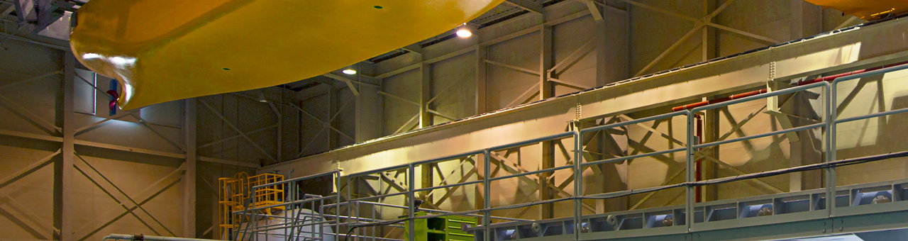
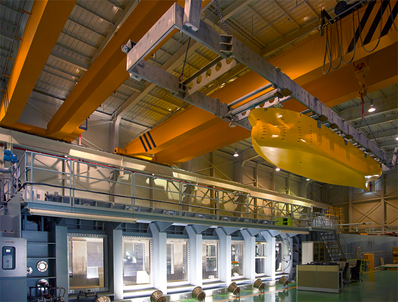
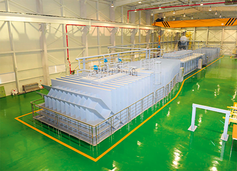
Test areas: Interaction between hull, thruster, rudder, and appendages, propeller cavitation inception speed test.
LCT specifications: Overall dimensions: 60 m × 22.5 m × 6.5 m (L×H×W). Test section dimensions: 12.5 m × 1.8 m × 2.8 m (L×H×W). Maximum flow velocity: 16.5 m/s.
Goals: The design and testing of high-value-added merchant ship propellers. Testing of special ship propellers such as large- and small-scale high-speed vessels and Korean-type submarines
RELATED ARTICLES
- To Safeguard The Payload: Redesign the launchpad
- Hydrophones In Gaseous Environment
- What Is Cavitation
RELATED PRODUCTS