JOHN VAUGHAN | BRÜEL & KJÆR
DOWNLOAD PDF
What is Static Balance?
Primary Balancing describes the process where primary forces caused by unbalanced mass components in a rotating object may be re solved into one plane and balanced by adding a mass in that plane only. This is known as Static Balancing as the object would now be completely balanced in the static condition (but not necessarily in dynamic).
What is Dynamic Balance?
Secondary Balancing describes the process where primary forces and secondary force couples caused by unbalanced mass components in a rotating object may be resolved into two (or more) planes and balanced by adding mass increments in those planes. This balancing process is known as Dynamic Balancing because the unbalance only becomes apparent when the object is rotating. After being balanced dynamically, the object would be completely balanced in both static and dynamic conditions.
What is the difference between static and dynamic balance?
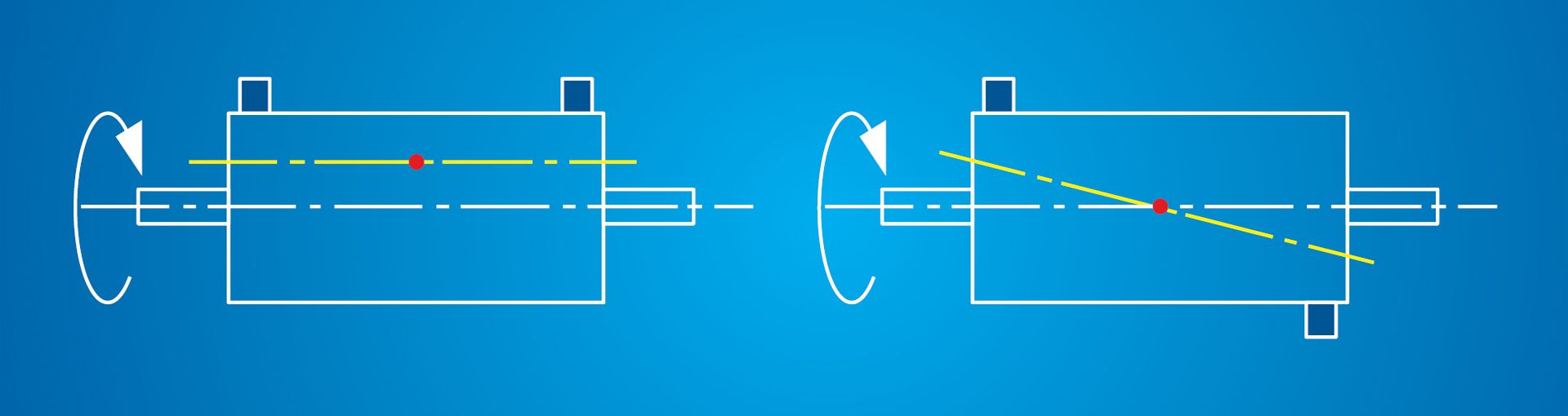
The difference between static balance and dynamic balance is illustrated in Fig.1. It will be observed that when the rotor is stationary (static) the end masses may balance each other. However, when rotating (dynamic) a strong unbalance will be experienced.
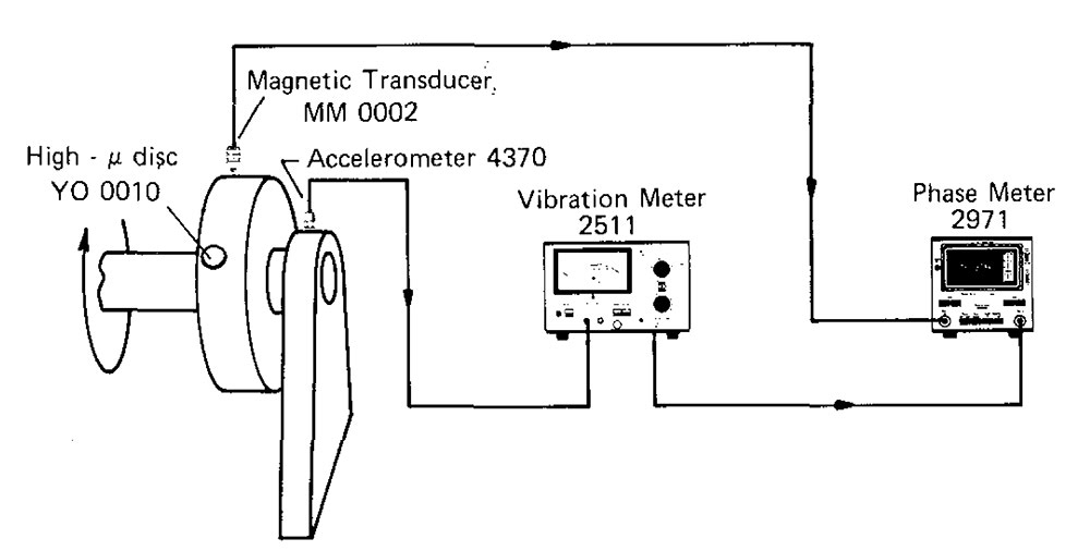
Standards of balance achieved by the arrangements shown here compare favorably with the results obtained from far more complicated and expensive balancing machines.
Rotor Balancing / Unbalanced Mass Components
An object that imparts vibration to its bearings when it rotates is defined as "unbalanced". The bearing vibration is produced by the interaction of any unbalanced mass components present with the radial acceleration due to rotation which together generates a centrifugal force. As the mass components are rotating, the force rotates too and tries to move the object in its bearings along the line of action of the force. Hence any point on the bearing will experience a fluctuating force.
In practice, the force at a bearing will be made up of a primary force due to unbalanced mass components in or near to the plane of the bearing, and a secondary force due to unbalanced couple components from the other planes.
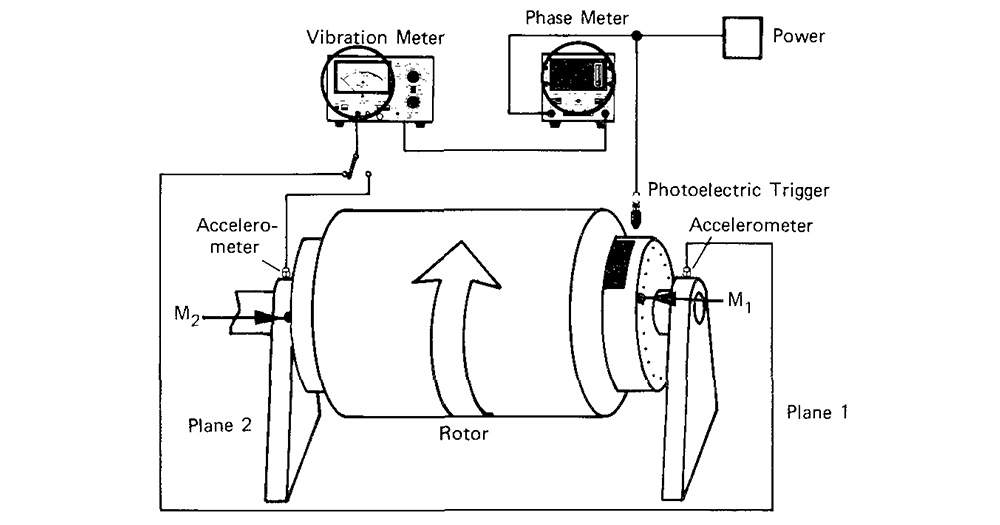
If an accelerometer is mounted on the bearing housing, the fluctuating vibration force can be detected, and an electrical signal sent to a vibration meter. The indicated vibration level is directly proportional to the resultant of the unbalanced masses.
The direction in which this resultant acts (i.e. the radius containing the centrifugal force) can be determined in an accurate way by comparing the phase of the fluctuating signal leaving the vibration meter with a standard periodic signal obtained from some datum position on the rotating object.
It is now possible to define the unbalance at the bearing by means of a vector.
The length is given by the magnitude of the unbalanced force (the measured vibration level) and the angle is given by the direction of action of the force. Further, if the resultant unbalanced force at a bearing can be resolved into its primary (first-order moments) and secondary (second-order moments) components, it will be possible to balance the object.
Measuring Static and Dynamic Balance
The vibration level can be measured in terms of acceleration, velocity, or displacement. However as most standards for balancing are written in velocity terms, a legacy of the days when vibration was measured by mechanical velocity-sensitive transducers, usually velocity will be the chosen parameter. The use of acceleration levels will tend to emphasize higher frequency components, while displacement will emphasize low-frequency components.
Continued in the full PDF: "Static and Dynamic Balancing" (Available for free download)
Download the full handbook
Please sign in to download.
Sign-up is free and gives you full access to our Knowledge Center, with guides, primers and handbooks, technical notes and more.