Vibration control software
Resonance search, track and dwell
A vibration controller feature used within a closed-loop test system to search for and track the resonant frequencies of any given payload. This is restricted to calculating the transfer function from one accelerometer position only; that is, to track one vital part of the payload.
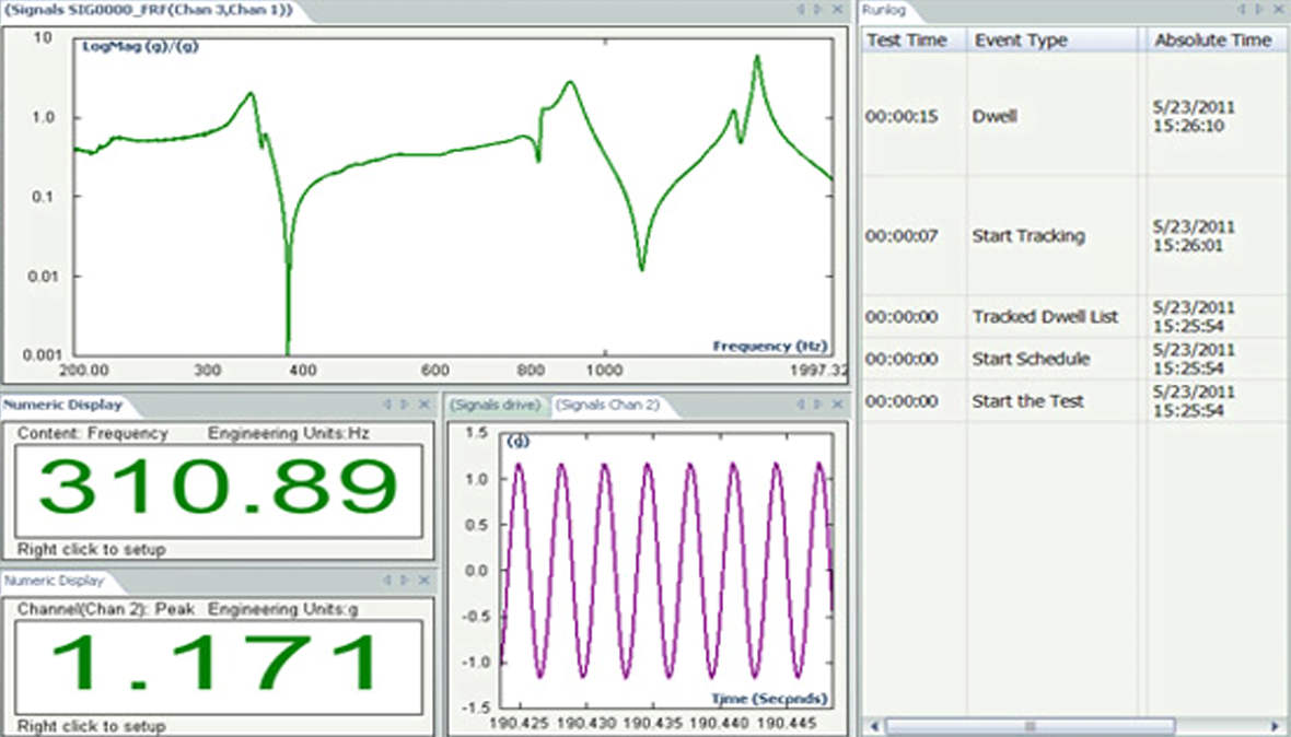
Solicitar ofertaResonance search, track, and dwell (RSTD) is an invaluable test for automated fatigue testing. A sine sweep is used to detect the resonant frequencies of the device under test (DUT). The test then dwells upon these frequencies for a specified period or number of cycles, automatically tracking changes in resonance occurring during the test in order to simulate a worst-case fatigue environment.
The resonant frequencies are determined by measuring the transmissibility of the closed-loop test system based upon user-specified values for minimum Q-factor (or damping factor) and amplitude.
USE SCENARIOS
- Fatigue and durability testing of a wide range of products and subassemblies
- Compliance with MIL-STD, DIN, RTCA and other standards requiring resonance dwell testing
CHARACTERISTICS
An RSTD test entails performing a sine sweep to search for a structure’s resonances, then dwelling at said resonances to investigate how the structure behaves. The setup for the sine sweep has all of the features of the sine vibration control whereby the user can specify the start and finish frequencies, sweep rate, and spectrum frequency resolution, namely, points per sweep.
The dwell duration can be specified in cycles or in time duration, with either a fixed or a tracked dwell. The tracked dwell adjusts the drive frequency to track the payload’s resonance, as its frequency changes during dwelling.
The user can specify the extent to which each resonant frequency is tracked in terms of either absolute frequency (Hz), percentage of resonant frequency, or rate of change (Hz per minute). The tracked dwell can be defined to stop the test after a certain percentage change from the original resonant frequency. It can also track changes based upon transmissibility amplitude ratios.
Plots of transmissibility magnitude and phase-versus-frequency are usually displayed, together with values for frequency, amplitude, Q and elapsed time for each resonance detected. The user can then manually add or remove individual resonant frequencies to be used during the dwell test.

Suscríbase a nuestro boletín informativo y recibirá las últimas noticias de B&K sobre sonido y vibración

