
Signal Conditioning and Amplification
Signal conditioning and amplification greatly improves the performance and reliability of your measurement system. From multi-pin signal conditioners for microphones, CCLD conditioners, and charge conditioners, our signal conditioning systems provide quality benefits to your setup.
Conditioning benefits


TABLE OF CONTENTS
1. Why Signal Conditioning?
2. Signal Conditioning for Acoustic Transducers
3. Signal Conditioning for Vibration Transducers
WHAT IS SIGNAL CONDITIONING
A typical signal conditioning system includes the signal conditioning hardware, which works as an interface between the raw signals and transducer outputs and the measurement device. In turn, a signal conditioning unit supplies functions such as signal amplification, attenuation, electrical isolation, filtering, powering, overload detection and Transducer Electronic Data Sheet (TEDS).
SIGNAL CONDITIONING HARDWARE
When deciding which conditioner to use, you should consider the type of transducer as well as the conditioner's benefits to the measurement system, including the following critical features and characteristics.
Number of Channels: For multi-channel tests, having more channels in the signal conditioner makes for a simpler system (for example, one power supply or battery for all the conditioned channels).
Channel Control: For units with adjustable settings, manual control is the easiest way to change configuration. In automated or multi-channel systems, computer control offers big time savings.
For very large systems, it is desirable to control as many channels as possible from a single PC.
WHY IS SIGNAL CONDITIONING NEEDED?
The signal conditioner's main task is to convert the picked-up signal into a higher-level electric one. The signal from the sensor that is generated might need to be converted to be usable and to suit the different instruments it is connected to. Any standard process signal can be achieved by converting any sensor signal.
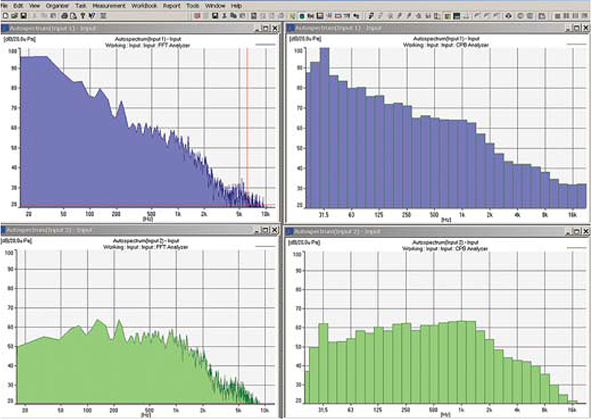
Besides needing to cover the measurement's frequency range, the analog filter of a signal conditioner can remove portions of the signal outside the range of interest.
For example, in-vehicle measurements of sound often have very strong low-frequency content below 20 Hz. A 20 Hz high-pass filter will attenuate the signal below the audio range which may improve the measurement system's noise floor at mid to high frequencies.
In addition to adjustable filters, signal conditioning offers gain control and other benefits:
Minimum and Maximum Gain: When using data acquisition system with adjustable input signal ranges, the noise floor of the complete measurement system (from transducer through conditioning to data acquisition) can be improved by adding gain in the conditioner.
Uni (Fine) Gain Adjustment: The sensitivity of a transducer in engineering units or volts typically varies significantly between individual transducers. Compensating for the individual sensitivities using fine gain control in the conditioner removes this error.
Transducer Electronic Data Sheet (TEDS): Significant measurement errors can be automatically avoided when the fine gain adjustment of the conditioner is read from the transducer's built-in TEDS support.
Multi-unit Rack: Assembling a rack for mounting is a convenient way of organising laboratory- based measurement systems where all the conditioning and data acquisition are combined. For most signal conditioners, you can order an optional 19-inch rack and/or a multi-unit frame, with which a single or more conditioner can be mounted together.
Signal Amplification:Increasing the signal (signal amplification) is a two-way process that is needed for digitalization or processing. The signal amplification can be carried out by either increasing the resolution of the input signal or by increasing the signal to noise ratio.
When using the LAN-XI DAQ System, you are provided with Dyn-X technology for unrivalled dynamic headroom.
SIGNAL CONDITIONING FOR ACOUSTIC TRANSDUCERS
For acoustic transducers, signal conditioning adds many benefits, such as:
Polarization Control: The working principle of the condenser microphone is based on a fixed charge. This charge is established, either with a very stable external polarization voltage, typically 200 V, via a large resistor, or by an electret layer deposited on the microphone's backplate, in which case the external polarization voltage should be set to 0 V.
What Is Charge Injection Calibration?
CIC (Charge Injection Calibration): CIC is a technique for on-line verification of the integrity of the entire measurement chain, for example, microphone, preamplifier and cabling. Even microphones remote from the input stage/conditioning amplifier can be verified.
The philosophy behind CIC is that if we have a known condition (for example, a properly calibrated microphone) and establish a reference measurement, then as long as the reference value does not change, nothing has changed, for example, the microphone calibration will still be valid.
Signal Filtering: A-, B-, C-, and D-weighting
A-weighting Filters
Sound measurements often specify A-weighting to reflect the acuity of the human ear, which does not respond equally to all frequencies. Using analog A-weighting filters can also have the same benefit of improving the measurement system's noise floor at mid to high frequencies for in-vehicle measurements.

B‐, C‐, and D‐weighting Filters
To accurately measure sound, one can also specify B‐, C‐ or D‐weighting instead of the more common A‐weighting. These additional weightings also reflect the acuity of the human ear, which does not respond equally to all frequencies, but also has a different response at different sound pressure levels.
SIGNAL CONDITIONING FOR VIBRATION TRANSDUCERS
AC Acceleration Output
AC Acceleration Output This is the “raw time” output from an accelerometer through any gain and filtering in the conditioner.
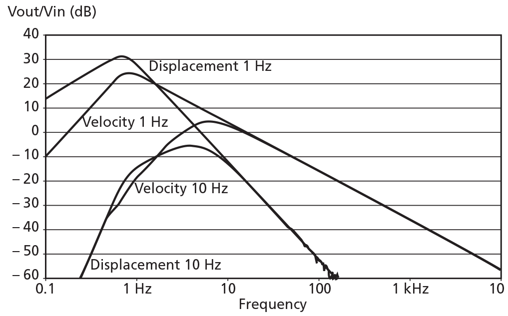
AC Velocity and Displacement Output (Single‐ and Double‐ integration Filters)
In some measurements, such as machine health monitoring according to ISO 10816, the velocity or displacement is of more interest than the acceleration from an accelerometer. A single and double integration filter easily converts an acceleration signal to velocity or displacement in the time domain.
Converting to velocity or displacement in the conditioner makes further analysis easier.
DC RMS and Peak Outputs and Alarms
Some analysis techniques use averaged (RMS) or Peak measurements instead of the “raw time” output signal. Conditioners with this capability are often called “measuring amplifiers” because they provide the needed measured parameter without need for additional instrumentation.
Besides being displayed on the unit’s screen, the averaged (RMS) or Peak values can be sent to other measurement devices as a DC voltage. A TTL alarm output can be sent from the measuring amplifier when a limit is exceeded.
WANT TO KNOW MORE?
For further details of the range, availability, and price, please use the link below to get in touch with your local Brüel & Kjær representative.

当社(ブリュエル・ケアー)へのお問い合わせについて
貴社のニースに合った製品をご紹介いたします。
計測機器の設置等のサポートを行います。
音響・振動などのご不明点についての回答、サポートを行います。