Vibration Control
Shock Response Spectrum
A vibration control feature used to synthesize a specified shock response spectrum (SRS) to measure a payload’s resistance to shock damage.
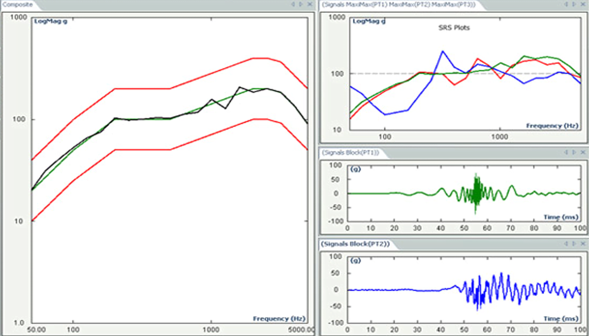
Request PriceSRS synthesis is used to evaluate the shock resistance of the DUT (device under test). This is achieved by synthesizing, within a closed-looped test system, a user-specified SRS profile of acceleration versus frequency in order to create complex transient waveforms for driving an electrodynamic shaker. The desired SRS profile is sometimes referred to as RRS (required response spectrum).
The test system takes advantage of the fact that many different transient waveforms can produce the same SRS profile; hence, parameters can be selected to account for the shaker’s capabilities and for likely damage to the DUT.
USE SCENARIOS
- Simulating shock transients, including pyrotechnic bursts and earthquake waveforms
- Shock damage testing, or shock damage risk analysis (SDRA), by matching a specified SRS profile
- Aerospace testing applications, such as reliability tests of electronic and mechanical components during explosive events
- Earthquake simulation and seismic qualification testing of buildings and other structures
- Packaging, shipping and transportation testing
- Reliability and durability testing of computer equipment, including shock tests of hard drives
CHARACTERISTICS
An add-on function of the classic shock profile, SRS synthesis and control enables a more aggressive and sophisticated shock test. It synthesizes a complex transient waveform from sinusoidal components, or wavelets, based upon a table of sine beats (or damped sine), with a wavelet used for each of the Nth octave bands.
An iterative process is used to automatically adjust the amplitudes, half-cycles, and relative delays of the wavelets until the SRS of the synthesized pulse matches the profile SRS, within the required accuracy. The generated time-domain shock can then be manually adjusted within a specified SRS fitting error to create a pulse that matches the test criteria, typically pulse duration. The desired shock pulse is saved for future reference and can be applied repeatedly and consistently.
The user creates an SRS profile by either entering or importing a breakpoint table of frequencies and acceleration amplitudes, plus abort limits. Also specified are the Q-factor (or damping) and the synthesis method as either pyroshock, minimum acceleration or user-defined duration.
SRS analysis typically covers up to a 14-octave range using maxi-max, negative maximum, and positive maximum analysis techniques. The user specifies high and low frequencies, reference frequency, damping ratio or Q value and resolution (1/1, 1/3, 1/6, 1/12, 1/24, 1/48).

Subscribe to our newsletter and receive the latest stories from our world of sound and vibration

