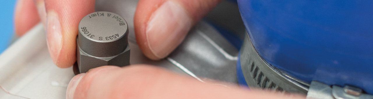
The Accelerometer Mounting Check (AMC) – based on Brüel & Kjær’s patented technology – provides an easier and faster way of testing accelerometer mounting and verifying, that your transducers mounted correctly, replacing lengthy visual and manual inspection.
Let’s dive into the details.
Perfect Accelerometer Mounting
The Theory Behind The Technology
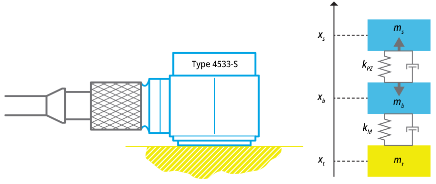
We model an accelerometer mounted on a structure as a mass-spring-damper system where ms, mb and mt are the seismic mass of the accelerometer, the mass of its base and the mass associated with the test object, respectively (Figure 1). The two first masses are connected by a spring with stiffness kPZ that represents the piezoelectric element.
ACCELEROMETER TYPE 4533-S
Figure 1: Type 4533-S and mass-spring-damper system
A spring/damper element kM is added to model the influence of the test object. The masses can move along the vertical axis, and their coordinates are xs, xband xt, respectively. The easiest way to derive the equations of motion is to use Lagrange’s equations.
First we construct the Lagrangian L=T-V, where T and V are kinetic and potential energy of the system:
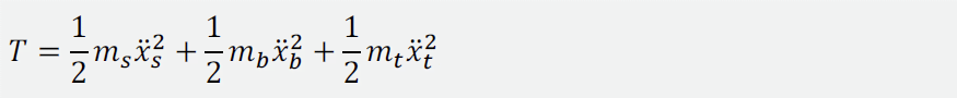
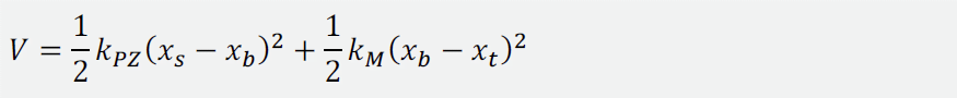
With no external forces acting on the system and omitting dissipation.
The Lagrange equation is:
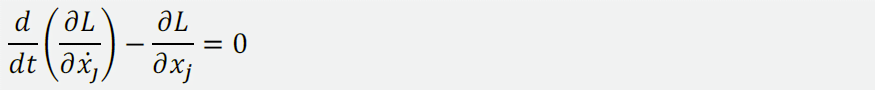
Where xj is one of the coordinates xs, xb and xt. Differentiation yields three equations of motions.
In matrix notation these are:
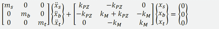
Or in a more compact format:

The system has three degrees of freedom (DOF), one of them being the rigid-body motion of the assembly. Following the AMC approach, a periodic electrical charge is applied to the piezoelectric element, making it contract and expand. This applies forces (denoted by the grey arrows in Figure 1) acting on the seismic mass and base.
Simultaneously, AMC measures the response of the accelerometer, which is proportional to the deformation of the piezoelectric element (xs - xb) and calculates the AMC FRF between the response and applied charge.
It is possible to obtain the AMC FRF analytically. As the elements of the matrix [α(ω)]=([K]-ω2 [M])-1 are the FRFs between the corresponding DOFs, the AMC FRFs can be combined from the elements of [α(ω)] = ([K] - ω2 [M])-1 are the FRFs between the corresponding DOFs, the AMC FRFs can be combined from the elements of [α(ω)].
Figure 2 illustrates AMC FRFs computed for three important scenarios: A properly mounted accelerometer, a free hanging accelerometer and the accelerometer properly mounted on a structure made of a light material (like wood) or on thin metal or plastic plate. Comparing the measured curves, AMC is able to detect the mounting quality.
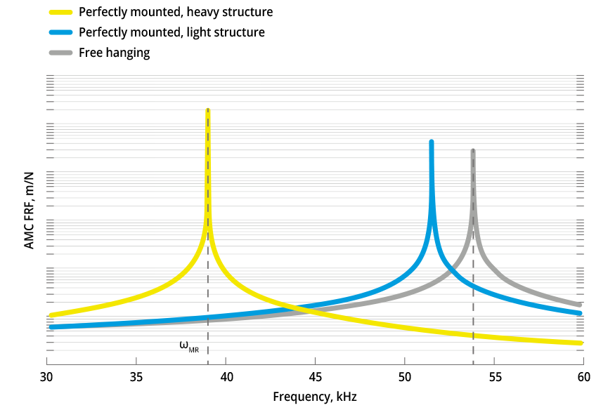
Figure 2: AMC frequency response functions
Analysing the Mounted Resonance Frequency
The plot sketches the AMC FRF (yellow curve) when the accelerometer is perfectly mounted on an infinitely heavy object (kM → ∞, mt → ∞). The FRF has a peak at mounted resonance frequency, ωMR2 = kPZ/ms. The grey curve represents the FRF of free hanging accelerometer (kM → 0); it has a peak at ωFH2 = kPZ (mb + ms) / (ms mb). For a typical accelerometer mb ≈ ms, and ωFH ≈ √2 ωMR, [Ref. 2].Before initiating AMC, one needs to make sure that the accelerometer is properly mounted on the structure. When initiated, AMC looks up the value of the mounted resonance frequency in the transducer database and generates a swept sine excitation in the range around ωMR (the white region).
The measured AMC FRF, which should be close to the yellow curve, is stored as a reference. Occasionally, the procedure is repeated, and the newly measured AMC FRF is compared with the reference curve.
If during the test, an accelerometer falls off the structure, its AMC FRF will rather look like the grey curve that corresponds to the free hanging accelerometer; the algorithm detects if the two curves significantly differ in the white region and asks the user to check the accelerometer mounting.
If the accelerometer is mounted on a structure made of light material, the reference AMC FRF may look like the blue curve (kM → ∞, mt small). In the white region, it is almost impossible to distinguish it from the free hanging AMC FRF, and thus the AMC can fail.
To prevent this, the BK Connect™ software introduces a pre-test wizard to recognize such situations.
Benefits of Accelerometer Mounting Check
- Avoid having to redo measurements due to loose transducers
- Save significant time checking transducers are correctly mounted
- Have increased confidence in your data quality
In addition, Accelerometer Mounting Check automatically verifies that accelerometers are working and whether the mounting has changed:
- It is built-in for all new S-type Brüel & Kjær CCLD accelerometers
- All charge accelerometers are supported when used with LAN-XI DAQ Modules
How Accelerometer Mounting Check Works
References: [1] Ewins, D.E. 2000. “Modal Testing: Theory, Practice and Application”, Research Studies Press Ltd., Baldock, England[2] Serridge, M., Licht, T.R. 1987. “Piezoelectric Accelerometers and Vibration Preamplifiers”, Brüel & Kjær Publications, Denmark
Iscriviti alla nostra Newsletter e ricevi le informazioni più recenti dal mondo del suoni e delle vibrazioni
Le ultime notizie Brüel & Kjær ti raggiungono con un solo click
Nuovi prodotti, sconti e offerte speciali
Articoli rigurdanti il suono e le vibrazioni, video e guide