One cannot find a fridge or washing machine in the shops that does not bear an energy label specifying, among other information, noise and sound power levels. The advantages of such labelling are considerable.
BK CONNECT ACOUSTIC CAMERA
Take the CE marking as an example. Businesses know that products bearing CE marking can be traded in the EEA (European Economic Area) without restrictions, and consumers enjoy the same level of health, safety, and environmental protection throughout the entire EEA.
However, before a product reaches the stage where it is ready for production and ready to have its sound power determined according to international standards, there is a good deal of noise engineering to be done in the Research & Development (R&D) and Quality Assurance departments.
Small and medium enterprises, in particular, are eager to detect annoying noise sources at the R&D stage using a minimum of investment. The simple technique of using a sound level meter to quantify the sound pressure level rarely provides enough information to suggest efficient design changes to reduce the radiated noise.
DOWNLOAD
Whitepaper
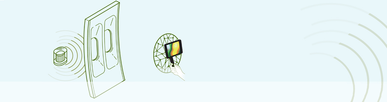
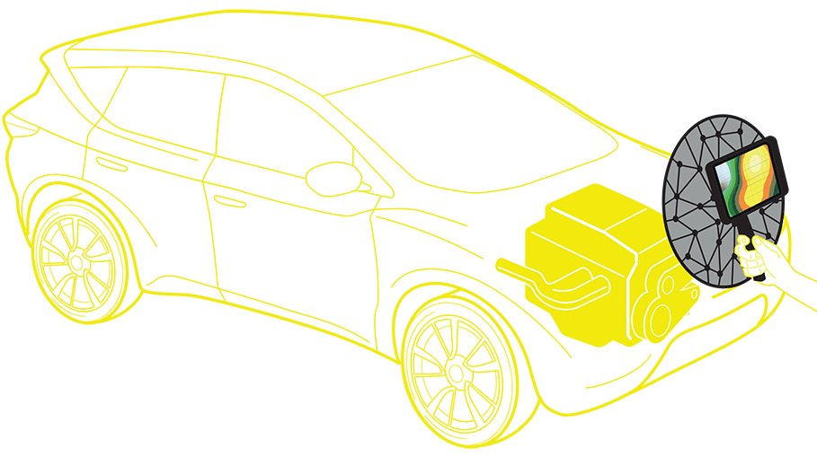
This could be where an acoustic camera could be of assistance. By combining an array of 30 microphones in a hand-held device, the BK Connect® Acoustic Camera from Brüel & Kjær gives the user a noise map of the device under test.
When using an Acoustic Camera the technician and the test engineer who have been assigned the task of improving the acoustics of the device, can see immediately where the sound is coming from.
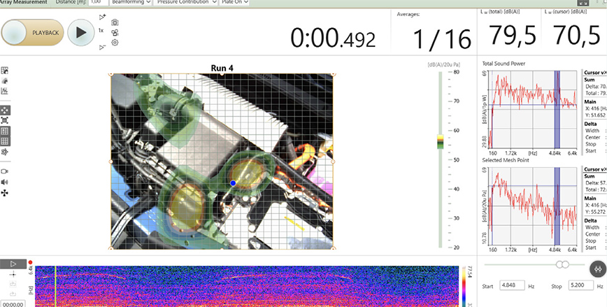
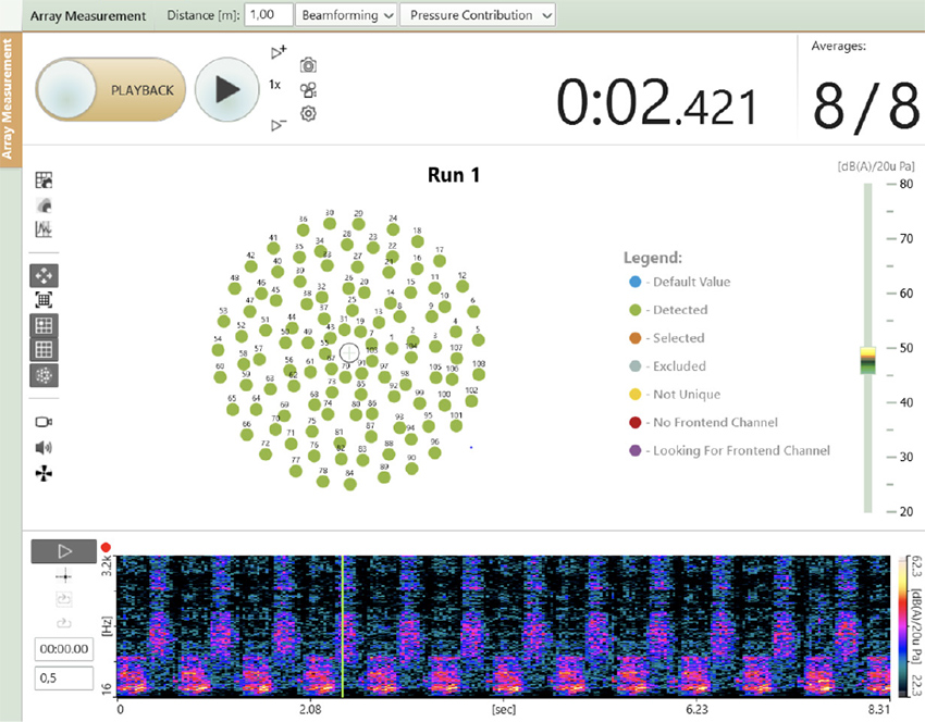
By knowing the position of the major sources, their spectral content and their relative sound power contributions, a good understanding of the root causes and radiation mechanisms can be obtained.
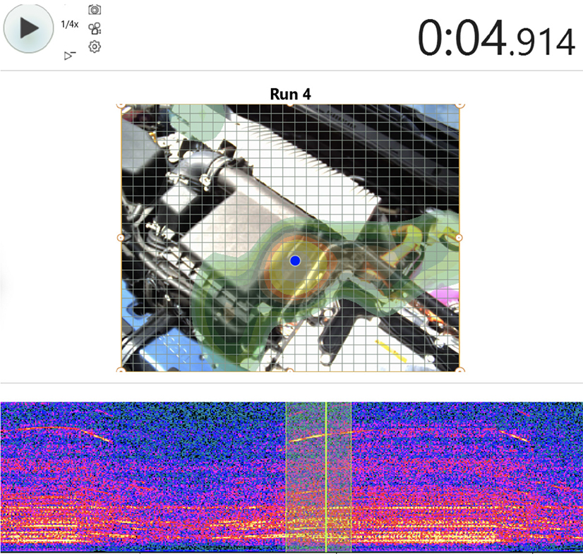
By using the time cursor in the spectrogram, attention can be focused onto individual events.
The job, however, is not finished here. The results of the tests have to be reported to colleagues, perhaps to management, proposed changes have to be implemented and tested again.
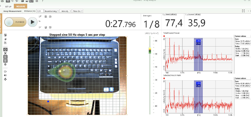
The Acoustic Camera can help here as well. Not only can it provide noise maps, but also spectrograms, sound power graphs and videos for documentation and comparison purposes.
Recorded tests can also be replayed at slower speeds to investigate short duration events. These features have shown their worth for troubleshooting, rattle detection and customer complaint evaluation.
Beamforming Measurements
To obtain an overview of a noise situation near to the device under test, the Acoustic Camera should ideally be positioned at about 35cm (one array diameter) from the source.The delay and sum beamforming technique, which is based on the time of flight of the acoustical signal from the source to the array, is then used to calculate a noise map as seen from the array.
This is known as the pressure contribution map. For beamforming measurements, the 30 microphones in the array are flush-mounted in a plate so that the disturbance from background noise is significantly reduced.
Holography Technique: Detailed Investigation
When a particular region has to be investigated in detail, the plate can be removed and the array positioned at 5cm (the average spacing between the microphones) from the device under test.At such a close distance the array microphones can detect all the amplitudes and phase information of both the propagating and the evanescent sound waves which enables a complete description of the sound field to be calculated; this is the holography technique.
The useful frequency ranges of these techniques do not cover the complete frequency range of interest of the noise engineer; the resolution of beamforming is related to the wavelength of sound and is, therefore, most useful at high frequencies whilst holography can be used at low frequencies, its resolution is set by the distance between the microphones.
However, for stationary noise, there is a solution called Wideband Holography. With Wideband Holography the data is measured with the array at 10cm from the device under test (twice the average spacing between the microphones) which is in between the ideal position for holography and for beamforming. The data is then transferred to the Array Acoustics Post-processing application which contains the WBH calculation. This patented algorithm provides excellent estimates of sound power levels at both low and high frequencies.
The resolution of beamforming is related to the wavelength of sound and is, therefore, most useful at high frequencies whilst holography can be used at low frequencies, its resolution is set by the distance between the microphones.
Using An Acoustic Camera in your R&D projects
To sum up, the BK Connect Acoustic Camera is a valuable tool for noise source identification well-suited for small to medium enterprises that have a well-defined job to be done. The range of industries addressed is huge, including automotive sub-suppliers of acoustic packaging, producers of weather seals, computers, pumps, and power tools manufacturers.
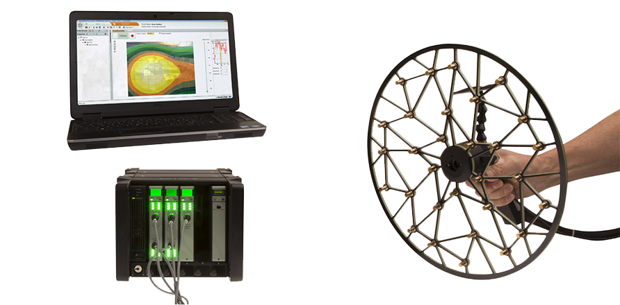
The functionality of the Acoustic Camera can be augmented if and when required with a larger array, or extra post-processing such as Wideband Holography or one of the many BK Connect applications such as Sound Quality Metrics.
An acoustic camera can be used with other arrays such as this large 106 channel array used for measurements on pumps.
Inscreva-se em nossa Newsletter e receba as últimas histórias do nosso mundo de ruído e vibração
As últimas notícias da Brüel & Kjær entregues na sua caixa de entrada
Lançamentos de novos produtos, descontos e ofertas especiais
Artigos, vídeos e guias sobre ruído e vibração