While CIC is not technically a ‘calibration’ method, the technique is sensitive to any change in the microphone cartridge’s capacitance and the connected preamplifier (and measurement cable), which indicates the microphone channel’s condition.

The Principle of Charge Injection Calibration
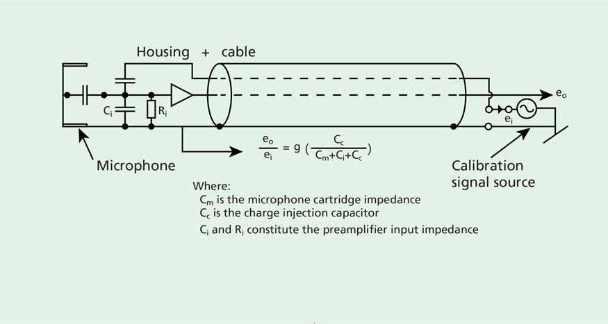
In CIC, a signal is introduced through a small, highly stable capacitor built into the preamplifier in series with the combination of the microphone cartridge and preamplifier input, see fig. 1.
The signal is divided between the small capacitor and microphone-preamplifier impedance, leading to an output approximately inversely proportional to the microphone cartridge capacitance. Any change in the microphone capacitance will be reflected in a change in the output from the measurement channel.
As the signal is introduced directly to the microphone cartridge, changes in the electrical part of the channel will also be reflected in the output. When the signal is turned off, the capacitor has a small contribution to the input capacitance of the microphone preamplifier with very little influence on the properties of the measurement channel.

Fault Detection Using CIC
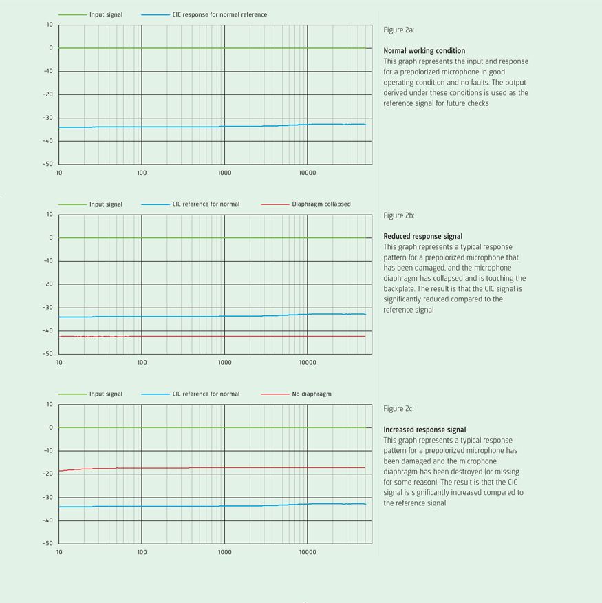
To use CIC, the measurement channel’s response to the CIC signal is registered for reference, while the channel condition is known. A signal is applied for verification, and the response is compared to the reference response. If there is no difference, it is an indication that the channel is still in good condition.
Deviation from the reference response strongly indicates a fault in the measurement channel, and an investigation of the channel is required. Typical faults that can be detected with CIC include broken diaphragms, short-circuited microphones, contact failure between cartridge and preamplifier, and cable breaks.

LEARN MORE
MICROPHONE CALIBRATION SYSTEM
Other faults may be detected with CIC, depending on how severe they are. Changes in diaphragm tension or polarization voltage directly influence the sensitivity and frequency response of the microphone, but such changes have a relatively small influence on microphone cartridge capacitance.
For example, a 2 dB change in the diaphragm tension of a typical sound level meter microphone changes its capacitance (and thus the CIC signal) by approximately 0.5 dB.
CIC is not a replacement for acoustical verification, but CIC can extend the interval between routine acoustical calibrations. Also, CIC is an excellent tool for registering severe faults, but is limited when checking for small sensitivity changes, and even less effective for checking microphone frequency response.
With high-quality, stable microphones, faults are likely to be due to events that significantly change the microphone. A stable CIC response is a reasonable indication that the measurement channel is functioning correctly. Our Calibration Systems provide automated primary and secondary calibration of all measurement microphone, hydrophone, and preamplifiers.
WHAT CIC ACTUALLY IS
CIC is not actually a ‘calibration’ method. The name was intended to emphasize its application. To avoid the use of electrostatic actuators in outdoor microphones – due to a risk of false alarms and damage to the microphone – insert voltage preamplifiers were used to check the electrical part of the channel.
These preamplifiers are normally used for open-circuit sensitivity microphone calibration. This method was termed insert voltage calibration (IVC). Later, microphone capacitance was included in the check, which was a leap forward in the channel check compared with the initial IVC method.

Iscriviti alla nostra Newsletter e ricevi le informazioni più recenti dal mondo del suoni e delle vibrazioni


