Fermilab is managed by the Fermi Research Alliance for the US Department of Energy and it collaborates with scientists from around the world to investigate neutrinos, which are among the most abundant particles in the universe.
Although neutrinos are all around us, and of great theoretical and experimental interest, they are very difficult to study.
What are Neutrinos - And Why Are They Important?
Neutrinos could provide the answers to some of the most fundamental questions about the nature of our universe: Why we exist and why the universe is filled with matter rather than light and radiation.
One of the strangest aspects of neutrinos is that they are able to oscillate – or change – from one type of neutrino to another.
As part of the Main Injector Neutrino Oscillation Search (MINOS) project, scientists are studying neutrino oscillation to see whether it can answer questions about the abundance of matter in the universe, or lead the way to new physics.
Intense Beams Of High-Energy Neutrinos
Because neutrinos in Fermilab’s experiment travel near the speed of light, physicists must place detectors far away to allow neutrinos time to oscillate. The MINOS project uses two detectors, one at
Fermilab in Illinois and the other located 450 miles away in Minnesota.
Fermilab’s particle accelerator produces intense beams of high-energy neutrinos and sends the beams to Minnesota, where a 6,000-ton steel detector searches for neutrinos that have changed flavour during the split-second trip, enabling scientists to study neutrino oscillations.
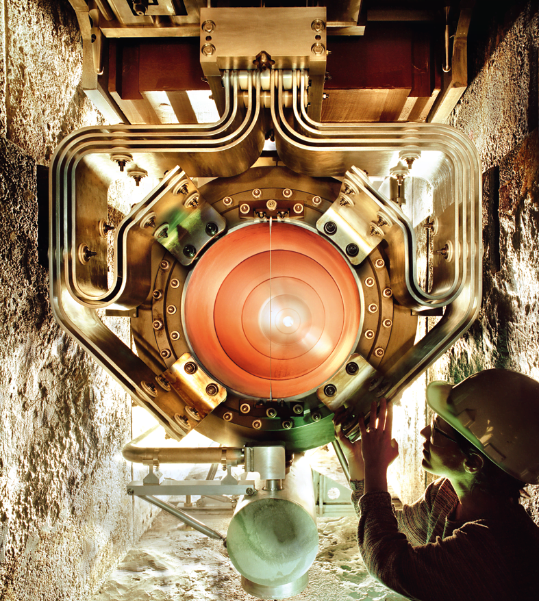
To manufacture neutrinos, sub-atomic particles called ‘pions’, which result from protons interacting with a target, are focused upon by two powerful magnetic horns and directed through a long decay pipe. During the time of flight in the decay pipe, the pions decay to a neutrino and a muon. The beam of neutrinos is not a continuous stream; it is a series of pulses.
The beam cycle time is every 1.33 seconds and 4E13 protons per pulse are delivered in each 10µsec batch, resulting in an average incident beam power of 400 kW. For each beam pulse, the magnetic horns experience an electrical pulse with 200 kA peak current lasting 2.3 msec to focus the pions from target interaction and place them on a trajectory through the decay pipe and on to the detector in Minnesota.
Power Increase Results in Design Change
The first beam of neutrinos was sent to Minnesota in 2005 and, over the years, the beam power has increased from 400 kW incident beam power to 700 kW. This increases the heating and thermal stress in the focusing horns and reduces the fatigue-life safety factor unless design changes are implemented to the horns.
In addition, the environment poses harsh conditions that accelerate corrosion and cause radiation damage that can decrease component lifetime.
Design changes were implemented to improve cooling and enhance fatigue life. The original specification for horn lifetime was 10 million pulses with a fatigue safety factor exceeding two.The lifespan of the new 700 kW horn was specified to exceed 50 million pulses, but after twenty-seven million pulses, a fracture occurred in the electrical bus stripline on the horn. The stripline is a complex structure with multiple unique boundary conditions and large variations in local modal damping.
Discovering The Root Cause
Kris E. Anderson, the lead project engineer at Fermilab, was in charge of finding the root cause of the problem. A vibration analysis project to characterize the dynamic response of the 700 kW horn stripline was set in motion.

The aim was to perform a full modal analysis – resulting in a set of modal parameters for the stripline assembly in the horn, measuring operating vibration data on the stripline conductors under typical operating conditions, and performing an analysis of operating vibration.
The measured data would then be used in analytical models to predict the useful life of the horn in terms of stress and strain, and extrapolate the results to provide an expected response of the full operating system.
ACCELEROMETERS / VIBRATION SENSORS
Experimental Modal Analysis (EMA) Model
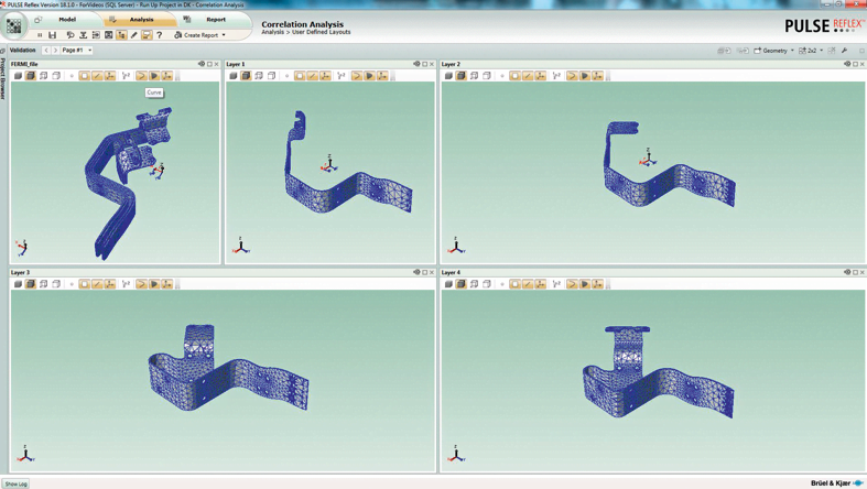
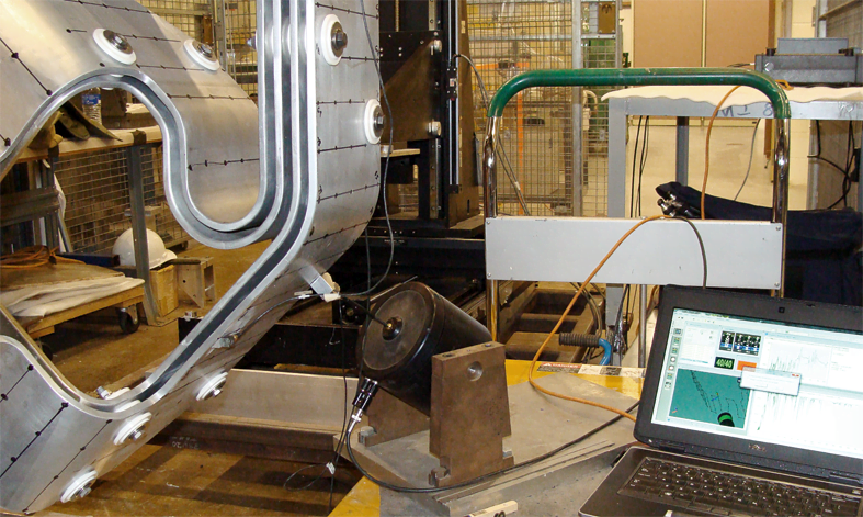
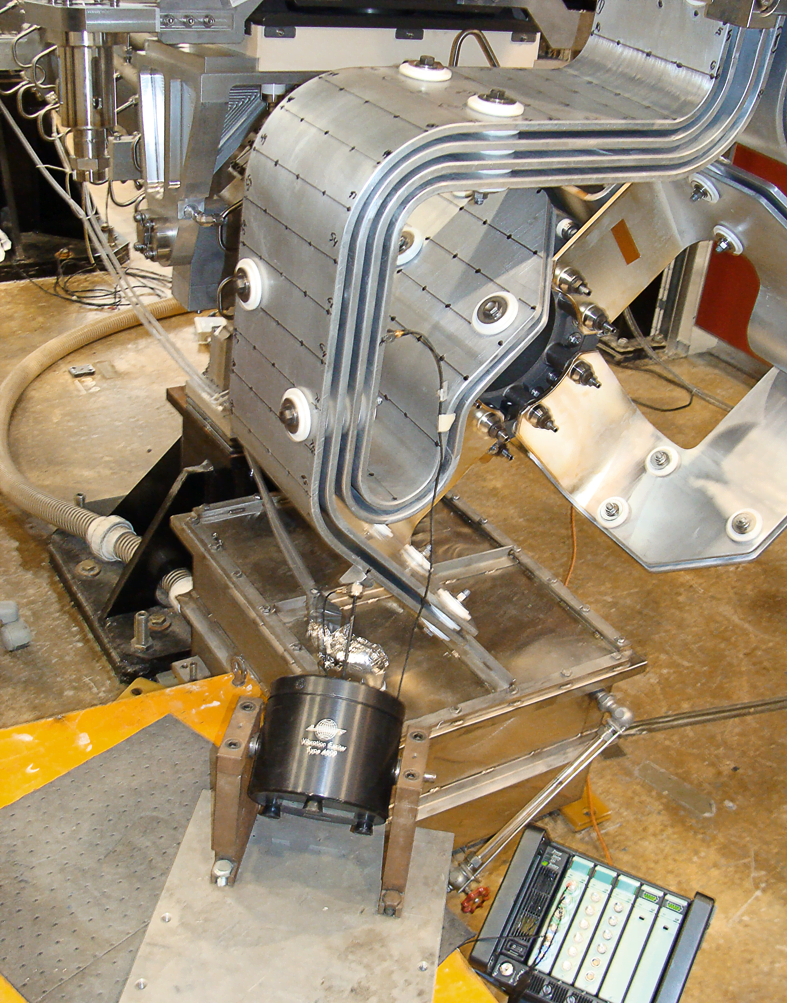
A spare 700 kW horn was used for the testing, geometry was created, and accelerometers set up. Using standard modal testing technology – including triaxial accelerometers, transducers and shakers – approximately 200 points were selected from an existing finite element analysis (FEA) wireframe model to create the experimental modal analysis (EMA) model.
These points were marked on the actual stripline conductor surface to guide the attachment of vibration transducers for live testing. A 10 lbf dynamic force shaker was used to excite the modes of the stripline.
During actual electrical pulse testing, three miniature triaxial accelerometers were mounted on the stripline to measure vibration, and the system was driven at 50, 100 and 200 kA. Time domain data was gathered and a frequency domain data reduction produced.
The subsequent set of frequency spectra were closely spaced in time (100 spectra per second for 8 seconds), producing a surface plot of time versus frequency versus amplitude.
Excessive Resonance
At the fracture location, the horn displayed lightly damped modes at 120 Hz and particularly at 424 Hz.
When driven by the electrical horn pulses every 1.33 seconds, these lightly damped modes led to increased local conductor displacements resulting from the electromagnetic conductor forces, and the modal ringdown in that region superimposed several hundred significant vibration cycles in between the 1.33 second cycle time.
In essence, the 27 million cycles to point of failure approached the gigacycle fatigue regime.
Reducing Displacement to Increase Operating Lifetime
Further testing using a clamp restraint in the relevant area successfully removed the destructive resonance.
Other design changes have been implemented to reduce the peak vibration displacements and shift modal frequencies higher, thus reducing displacement and subsequent conductor stress. The data has provided insight to address the problem in the current design and help enhance fatigue safety factor in future designs. Plans include conducting modal testing and vibration measurements on future proposed stripline designs, to further understand the complex nature of the stripline response.
Kris Anderson comments: “We expect that an improvement in the lifespan of the next generation of horns has been increased by a factor of 2. By examining the modal data, future designs could have a significantly longer life.”
Get more knowledge about neutrinos and Fermilab (2:05):
Related Accelerometers
Related WAVES Articles

Suscríbase a nuestro boletín informativo y recibirá las últimas noticias de B&K sobre sonido y vibración


